Home
/ Blog /
WebRTC TURN server: Everything you need to knowWebRTC TURN server: Everything you need to know
October 17, 202211 min read


Share


We know that WebRTC powers almost every kind of live video solution imaginable these days. It is estimated that almost 20% of WebRTC call connections require a TURN server to connect, whatever may the architecture of the application be. Even the latest WebRTC ingest and egress standards—WHIP and WHEP make use of STUN/TURN servers. In this article, we’ll discuss everything you need to know about STUN and TURN servers. We will also try to deploy and test a popular open-source TURN server in the end.
The need for STUN/TURN Servers
Depending on the architecture, WebRTC creates a connection between peers directly or with a media server in the middle. But sometimes, a direct connection to other peers or the media server itself may fail at times. This can happen mainly because of 2 reasons - NAT and Firewall. We will briefly look into them here.
NAT (Network Address Translation)
The Network Address Translation is a mechanism that maps the public transport address into the private transport address of a device within its local network and vice-versa. A NAT usually lives on a router that sits between the local network and the internet.
A Transport address is nothing but the combination of an IP address and a port number. It is used to uniquely identify a device for communication.
NAT was designed to offer security and help conserve IPV4 addresses over the internet. But it also came with a few issues with respect to direct connection:
- The host device behind a NAT only knows its own private IP address. This makes it difficult to communicate with others outside the device’s local network since the private IP address (and transport address) is basically useless elsewhere.
- Hole punching is not supported when the target NAT’s mapping behavior is “address-dependant” or “address-and-port-dependant”, as defined in RFC4787 standard. In short, hole punching is a networking technique generally used for establishing a direct peer-to-peer (P2P) connection.
Firewall
Every host device has its own firewall that regulates all the incoming and outgoing network traffic for security purposes. Many enterprise firewalls simply block UDP traffic, as it is not as secure as other transport layer protocols such as TCP.
Since, WebRTC uses UDP for all of its media sessions to optimize for performance, there is a high chance that it may be blocked too. Sometimes, the firewall might also find other peers suspicious, blocking them from establishing a direct connection.
WebRTC uses ICE (Interactive Connection Establishment) framework to find the best path to connect the peers. When the direct connection fails, there must be a way for the peers to establish a connection. This is where STUN and TURN come into picture. Based on several parameters, the ICE framework will automatically try to use the configured STUN and/or TURN servers, when a direct connection is impossible. How ICE works is a whole other beast, which I'll cover at a later date. But here is an article that explains it pretty well, if you want to check it out. For now, let us focus only on the STUN and TURN servers.
Intro to STUN and TURN Servers
To understand how these servers help in establishing a connection, let us first try to understand what a STUN server and a TURN server does.
STUN Server
STUN is a network protocol used to retrieve the public IP address (or Transport address) of a device behind NAT so that the device can communicate after knowing its address on the internet. Usually, a STUN server is requested by the peer to know its public IP addresses (or specifically its transport address). Then, the retrieved address is used to communicate with devices outside its local network.
TURN Server
Sometimes, a direct connection is not possible due to NAT restrictions or a firewall blocking a connection, even with the help of the STUN server. The only way for peers to communicate in this case, is by routing the media through a relay server. A TURN server is used for cases like this.
TURN is a network protocol that enables a server to relay data packets (media in this case) between peers when no direct connections are possible. The peers may route media to the TURN server which will relay it to the other peer continuously.
TURN servers are usually referred to as Relay Servers. According to the RFC8656 specification, TURN is considered an extension to the STUN. So, a typical TURN server would include a STUN server implementation by default.
Internal Working of a TURN Server
Before trying to understand the operations of a TURN server, let’s take a look at some terminologies involved.
There are 2 participants associated with a TURN session:
- Client (TURN Client) - A host attached to the TURN server for communication. It interacts with the server following the specification by sending TURN messages.
- Peers - The hosts that the client wishes to communicate with. The TURN server relays the traffic between the client and the peers. Every peer interacts with the server like it usually does with other peers.
The Transport Addresses associated with TURN clients and Peers:
- Host Transport Address - The actual transport address of a client or a peer. It consists of the private IP address within its local network.
- Server-Reflexive Transport Address - The transport address of a client or a peer that is visible from the outside of its NAT. It consists of the public IP address outside the local network. This address is allocated by the NAT to correspond to a specific host transport address.
The Transport Addresses associated with a TURN server:
- Server Transport Address - The transport address of the TURN server that is used for sending TURN messages to the server. This is the transport address that the client uses to communicate with the server.
- Relayed Transport Address - The transport address of the TURN server that is used for relaying packets between the client and a peer. A peer sends data to this address on the TURN server, and the packet is then relayed to the client.

Summary of TURN server Operations
The TURN client already has access to the Server Transport Address of the TURN server, from the ICE server configuration in the case of WebRTC. The TURN server can only sense the Server-Reflexive Transport Address of the client (and peer) and not the Host Transport Address.
This happens when there’s a NAT in the middle, that maps the Server-Reflexive Transport Address to the Host Transport Address for the client/peer. When there’s no NAT in the connection, there’s no need to differentiate the addresses and it can simply be called Transport Address.
Every TURN client is assigned its own Relayed Transport Address for relaying the data. The peers will receive the data from this address and any data that the peers send to this address will be relayed to the respective TURN client that was allocated that address.
Transport Protocols
The following table illustrates the protocols used for transport between a TURN client to a server and TURN server to a peer.
| TURN client to TURN server | TURN server to peer |
|---|---|
| UDP | UDP |
| TCP | UDP |
| TLS-over-TCP | UDP |
| DTLS-over-UDP | UDP |
According to RFC8656 specification, the communication between the server and a peer always uses UDP. This is very helpful in case of WebRTC. Since the media sessions use UDP for transport, a peer doesn’t have to differentiate between another peer and the TURN server to communicate with it.
And if the client blocks UDP traffic completely, there’s always room to use other transport protocols like TCP, TLS-over-TCP, and DTLS-over-UDP. But, what happens if both the client and a peer happen to block UDP traffic? We will come back to that in a later section.
Now let us try to understand the exact steps involved in using a TURN server to achieve connectivity among peers. The peer that cannot participate in a direct connection is usually the TURN client and it will initiate the process.
1. Preparing to Send Data to Peer
A client can use TURN commands to create and manipulate an ALLOCATION on the TURN server, by communicating with the server on its Server Transport Address. An ALLOCATION is basically a “TURN Session” associated with the client. Among other things, every ALLOCATION has a corresponding Relayed Transport Address to be used.
The Relayed Transport Address is the address that the other peers can use to interact with. A peer can use the address to relay the data to the client. Additionally, the source of the data from the client relayed to the peer will be the Relayed Transport Address from the peer’s perspective.
2. Preparing to Receive Data from Peer
When the peers send data to the Relayed Transport Address, it’ll be matched with the ALLOCATION and be relayed to the client who is associated with it. But the data is discarded until a PERMISSION is created for the peer to send data to the client.
The PERMISSION for a peer can be created by the client, by using the address of the peer as it appears to the TURN server. The peer can get this address by sending a STUN Binding Request to the same TURN server (not any other STUN/TURN server) and then forward send it to the client by other means. ICE Candidates are used to handling this in the case of WebRTC. Once this is done, the peer can start communicating with the client through the TURN server.
The reason that the peer has to send a STUN Binding Request to the same server is, the transport address the peer got from a different STUN server, may not work for the target TURN server. This happens when the mapping behavior is either “address-dependant” or “address-and-port-dependant”.
3. Sending and Receiving Data from Peers
Now, the TURN is ready for relaying data between the client and peers. There are 2 mechanisms for sending and receiving data from peers through the relay server.
a. Send and Data Mechanism
In this mechanism, SendIndication and DataIndication messages are used to relay data between the client and the peers.
The client sends a SendIndication message to the server which contains the data and the peer information the data has to be relayed to. The server forms a UDP Datagram using that message and sends it to the respective peer.
Similarly, when a peer sends a UDP Datagram to the server, it is then converted into a DataIndication message and is relayed to the client.
b. Channel Mechanism
In this mechanism, a Channel is created for communication between a client-peer pair by using both their Transport Addresses once. There is no need to specify the Transport Address when sending data, unlike in the Send and Data mechanism. This mechanism is recommended when there’s a need for sending lots of data, mainly due to its smaller packet size.
The client creates a channel by sending a ChannelBind request with the peer’s Transport Address and a unique ChannelId. The communication between the client and the server is done by the use of ChannelData messages that contain a ChannelId and data among other things. The ChannelData message is converted to a UDP Datagram and sent to the peer. Similarly, any data received from the peer corresponding to a channel is packaged into a ChannelData message before being relayed to the respective client.
4. Maintaining the TURN Session
Every ALLOCATION has a LIFETIME attribute, denoting the time after which it will expire. The client has to send a refresh request to keep its ALLOCATION alive.
TURN Usage
There are mainly 2 ways a TURN server can be used to achieve connectivity. We will look into them by considering one-on-one connections as an example.
- One client with a single Allocation and one peer.
- Two clients with respective Allocations.
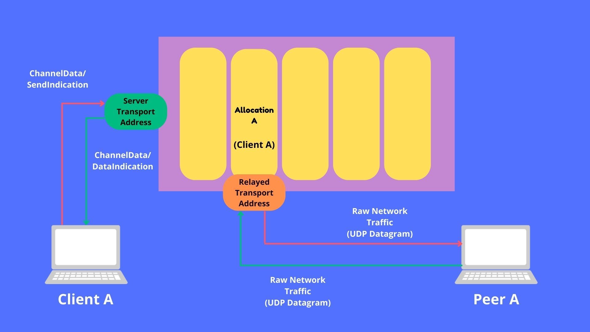
One client with a single allocation and one peer
In this case, there is one TURN client and one peer. Usually, when only one party has issues with the direct connection, this is the recommended way.
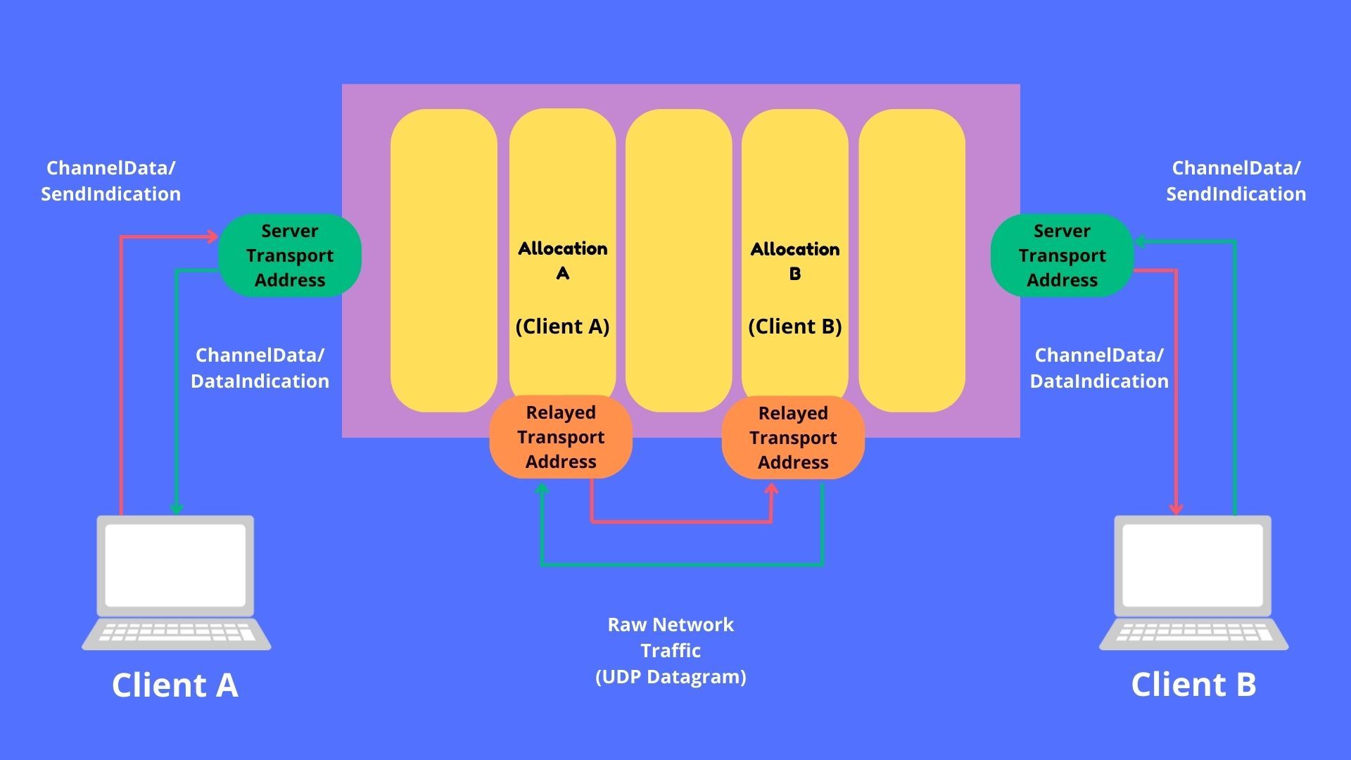
Two clients with respective allocations
In this case, both parties are TURN clients communicating with each other. This is the solution when both parties don’t support direct connection and that includes blocking UDP traffic.
Now that we’ve seen too much theoretically about the TURN server, let us also try to set up and test our own TURN server. We will be using coTURN, a really popular open-source TURN server implementation.
Setting up a TURN Server with coTURN
In this section, we will set up our own TURN server on Ubuntu (and similar Linux based OSes), using coTURN. We will do it in the following steps:
- Installing coTURN
- Configuring coTURN
- Testing the TURN server
1. Installing coTURN
First, create an AWS EC2 instance or a GCP Cloud Compute instance of Ubuntu OS. We will be installing hosting the TURN server in this instance. Then, connect to the instance with the help of SSH.
Run the following commands to update the repo and install coTURN.
sudo apt-get update
sudo apt-get install coturn
To make sure that coTURN always runs at startup, edit the file /etc/default/coturn.
sudo nano /etc/default/coturn
Inside the file, find the line TURNSERVER_ENABLED=1 and uncomment it. Now start the coTURN server by running the following command.
systemctl start coturn
2. Configuring coTURN
Before modifying the configuration file it is recommended to copy the original configuration file in case something goes wrong.
mv /etc/turnserver.conf /etc/turnserver.conf.backup
sudo nano /etc/turnserver.conf
Now, proceed to edit the configuration file and replace it with the below settings.
realm=<Your Domain>
server-name=turnserver
fingerprint

listening-ip=0.0.0.0
external-ip=<External IP Address>
listening-port=3478
min-port=10000
max-port=20000

user=testname:testpass
lt-cred-mech

log-file=/var/log/turnserver.log
verbose
After finishing the changes, you can restart the coTURN server with the following command.
sudo service coturn restart
3. Testing the TURN server
Now that we’ve installed and configured a TURN server with coTURN, it is time to test if it works correctly. One of the easiest ways to do this is to use this site that checks for Trickle ICE functionality.
First, add the STUN and TURN information in the following format. For STUN server URI stun:<IP Address>:<Port> and for TURN URI turn:<IP Address>:<Port> with the username and password configured before. Then, click on the “Add Server” button.
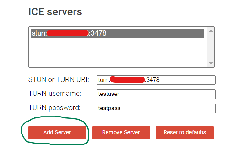
Once everything is set, you can start the test by clicking on the “Gather Candidates” button.
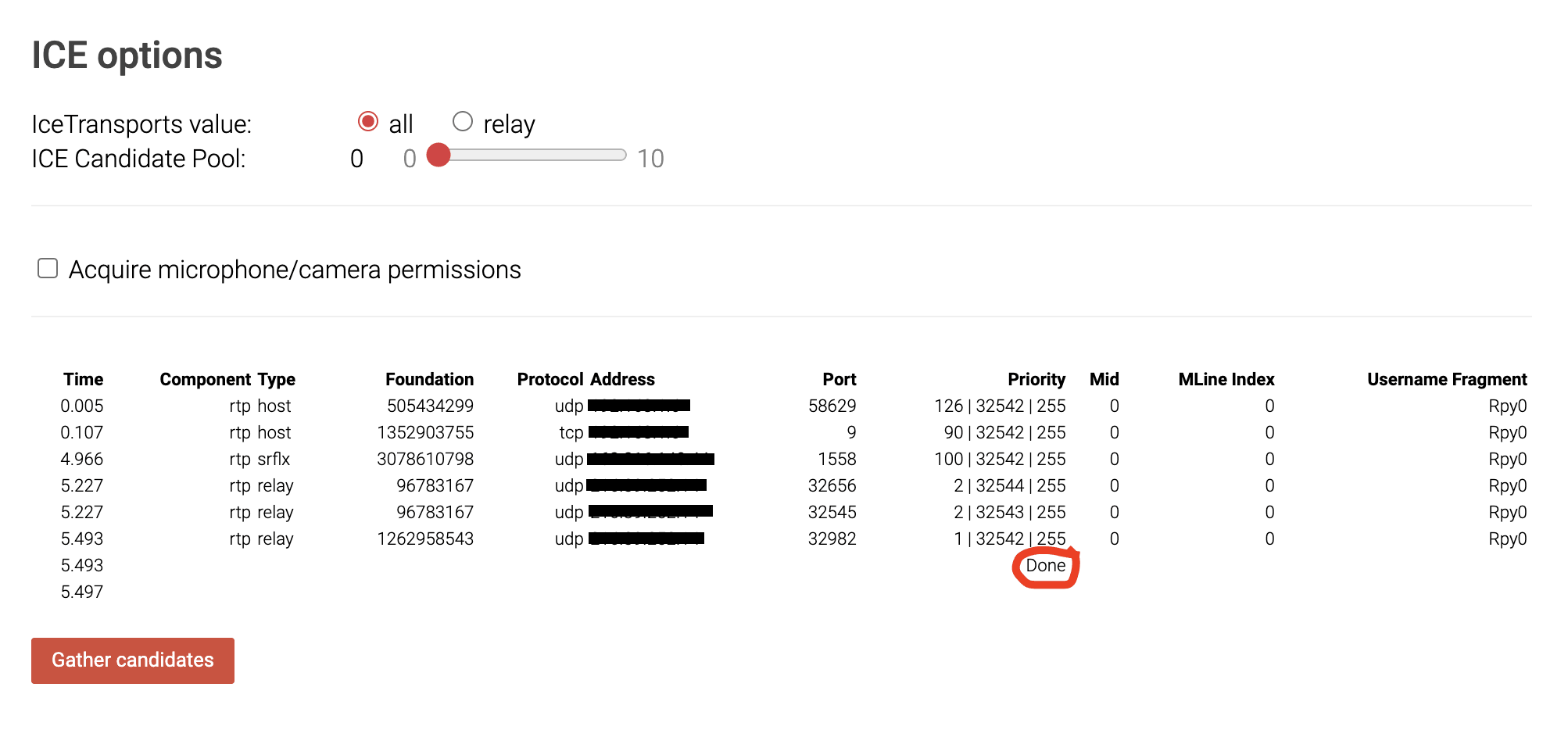
If your results look similar to the one in the image above without any fatal errors below the button, then the TURN server is working as expected.
Special Mention: If you’re trying to build a custom TURN server/client tuned for your use case, check out pion TURN. It is open source and has great support from the community.
Now that you know everything you need about TURN servers and the role it plays in your WebRTC call, you might as well try building a simple WebRTC app with this guide I wrote.
Reference
Basics
Share
Related articles
See all articles